TeTe Motor
An Industrial Gear Motor combines an electric motor with a gearbox to deliver controlled speed and useful torque. That combination can make a compact conveyor, mixer, or packaging line easier to drive. Picture a loaded belt starting smoothly instead of surging. The right unit can also reduce the need for separate transmission components.
Selection still depends on the application. Engineers compare output speed, required torque, duty cycle, mounting position, operating environment, and service access. A motor that fits the power rating may still be a poor choice if it overheats during frequent starts or struggles with shock loads. Small details matter. A dusty plant floor, limited clearance, or difficult lubrication access can change the decision.
As an illustrative expert voice—not a verified quotation from a real individual—industrial drive application engineer Alex Morgan might put it this way: “Choose the gear motor for the load and operating cycle, not just the nameplate power.” That principle frames why buyers consider an Industrial Gear Motor: it can provide dependable, application-specific drive performance when correctly sized and maintained. Yet no component is automatically efficient or trouble-free. Actual results depend on installation, alignment, controls, and maintenance. It is worth checking these assumptions before specifying a unit. A little uncertainty remains until the real load profile is measured.
Why Choose an Industrial Gear Motor?
What Is an Industrial Gear Motor, and How Do Its Components Work?
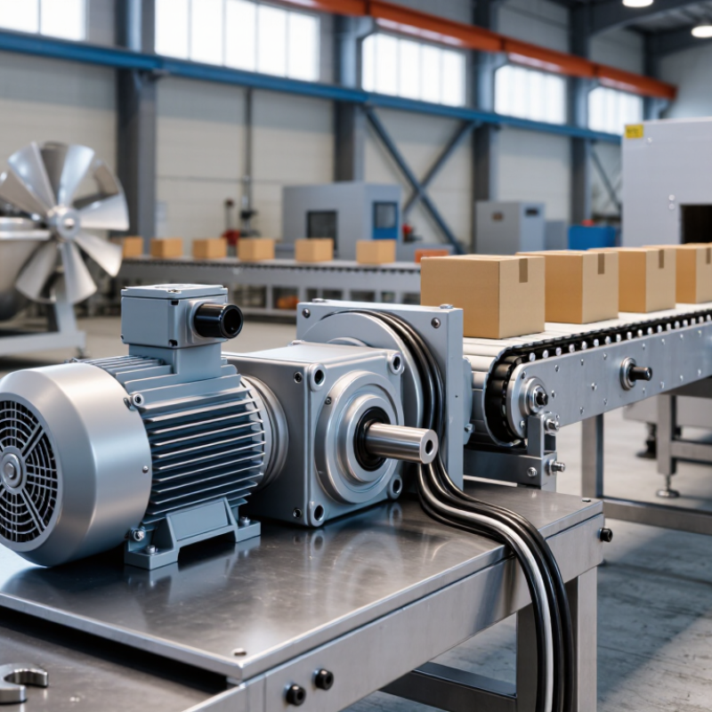
An industrial gear motor combines an electric motor with a gearbox in one drive unit. The motor supplies rotation; gears reduce output speed and increase torque. That matters. A conveyor moving heavy cartons, for example, may need a slow, steady shaft rather than the motor’s faster rotation.
Inside, the motor’s rotor turns within a magnetic field. A coupling transfers that motion to the gearbox, where meshing gears change speed and torque. Bearings support rotating shafts, while seals help keep lubricant in and contaminants out. The housing holds the assembly and sheds heat. Small details count. Incorrect alignment or low lubricant can raise vibration and temperature, even when the motor sounds normal.
The U.S. Department of Energy’s 2014 report, Improving Motor and Drive System Performance, estimates that motor-driven systems use about 68% of electricity in U.S. manufacturing. That figure covers systems broadly, not gear motors alone, but it shows why drive selection matters. Choose a unit by checking required torque, speed, duty cycle, mounting, and starting loads. A catalog ratio alone is not enough. Real shock loads and hot surroundings can change the choice, so verify operating conditions and maintenance access before installation.
| Category | Component or Parameter | What It Does | Typical Data or Selection Notes |
|---|---|---|---|
| Basic definition | Industrial gear motor | Combines an electric motor with a gearbox to provide lower output speed and higher torque than the motor alone. | Commonly used in conveyors, mixers, packaging equipment, and material-handling systems. Ratings and configurations vary by application. |
| Power source | Electric motor and stator | The stator creates a rotating magnetic field that drives the rotor, converting electrical energy into mechanical rotation. | Three-phase AC motors are common in industrial installations. Supply voltage, frequency, and motor speed must match the system requirements. |
| Drive connection | Rotor and input shaft | The rotor turns with the motor shaft and transfers input rotation to the gearbox, either directly or through a coupling. | Motor speed depends on motor design, supply frequency, and load. A four-pole AC motor commonly runs near 1,500 rpm at 50 Hz or 1,800 rpm at 60 Hz, with actual speed affected by slip. |
| Speed reduction | Gear stages and gear ratio | Meshing gears reduce rotational speed and transmit torque. Multiple stages can provide greater reduction in a compact assembly. | Output speed is approximately motor speed divided by the total reduction ratio. For example, 1,500 rpm ÷ 30:1 = 50 rpm. |
| Gear types | Helical, bevel, planetary, or worm gears | Gear geometry determines how power is transmitted and influences efficiency, noise, available ratios, and shaft arrangement. | Helical gears suit many general-purpose drives; bevel gears change shaft direction; planetary designs offer high torque density; worm gears provide right-angle drive and high reduction in a compact layout. |
| Torque transmission | Output shaft and bearings | The output shaft delivers rotation to the driven machine. Bearings support the shafts and help maintain gear alignment under load. | Approximate output torque = motor torque × reduction ratio × gearbox efficiency. With 2 N·m input torque, a 30:1 ratio, and 90% efficiency, estimated output torque is 54 N·m. |
| Lubrication and protection | Gear lubricant, seals, and housing | Lubricant reduces friction and wear; seals help retain lubricant and limit contaminant entry; the housing supports and protects internal parts. | Lubricant type, fill level, service interval, and housing orientation must follow the specific unit’s instructions and operating conditions. |
| Speed control | Variable-frequency drive (optional) | A compatible drive varies the frequency supplied to an AC motor, allowing controlled changes in motor speed and acceleration. | Check motor and drive compatibility, required speed range, cooling at low speed, and whether the application needs braking or feedback. |
| Application sizing | Load, duty cycle, and service factor | These factors determine whether the gear motor can handle steady running, starts and stops, shock loads, and the required operating life. | Select using required output speed and torque, load inertia, starts per hour, ambient conditions, mounting position, and the manufacturer’s rating method. |
Values shown are general engineering examples, not guaranteed ratings; actual performance depends on the specific gear motor, installation, and operating conditions.
It combines an electric motor and gearbox in one drive unit. The motor turns; gears slow the output and raise torque.
A rotor spins inside a magnetic field. A coupling carries that motion to meshing gears, which change speed and torque.
Bearings support rotating shafts, and seals help retain lubricant while blocking contaminants. The housing holds the parts and sheds heat. Small details matter.
A conveyor carrying heavy cartons may need a slow, steady shaft. A faster motor output alone may not suit that task.
Check torque, speed, duty cycle, mounting, and starting loads. Consider shock loads, hot surroundings, and maintenance access too.
Incorrect alignment or low lubricant can raise both. A normal sound does not prove everything is fine.
They describe motor efficiency classes: IE1 is standard, IE2 high, IE3 premium, and IE4 super-premium. Thresholds depend on power, pole count, and supply frequency.
No. The class applies to the motor, while gears and lubricant add losses. I would not rely on the label alone; load and operating hours matter.
An Industrial Gear Motor combines an electric motor with a gearbox to deliver controlled speed and torque for demanding equipment. The motor supplies rotational power, while the gearbox—typically made up of gears, shafts, bearings, and a housing—adjusts that power to suit the application. A higher gear ratio reduces output speed while increasing available torque, allowing machinery to move heavier loads at a controlled pace.
Shaft torque can be estimated using T = 9,550 × Power (kW) ÷ Speed (rpm), with the result expressed in newton-metres. Motor efficiency classifications under IEC 60034-30-1 include IE1, IE2, IE3, and IE4 for applicable motors within the standard’s rated-power scope, which extends from 0.12 to 1,000 kW. Industrial gear motors are commonly selected for conveyors that move materials, mixers that need steady rotational force, and lifting systems that require reliable, controlled motion. The appropriate unit depends on load, speed, operating conditions, and efficiency needs.