Why Choose a Customized Gear Motor?

Time:2026-10-14 Author:Amelia
0%

Why Choose a Customized Gear Motor? The answer begins with the machine, not the catalogue. Standard motors may fit ordinary equipment, but demanding systems often require a closer match. A Customized Gear Motor can be designed around torque, speed, voltage, mounting space, duty cycle, and noise limits. These details matter on the factory floor.

Eugen Elmiger, a respected motion-system executive at maxon, has expressed a useful principle: “The application defines the motion solution.” That idea reflects real engineering practice. A motor driving a medical pump needs controlled movement and quiet operation. A conveyor motor may require steady torque, sealed housing, and long service life. A robotic joint may need compact dimensions and precise feedback. Each application creates different priorities.

Small changes can matter.

Customization can reduce wasted space and improve energy use. It may also simplify installation when shaft geometry, connectors, or mounting holes match the equipment directly. Engineers can select suitable materials and gear ratios before performance problems appear. However, customization is not automatically better. It can increase design time, testing requirements, and production cost. A poorly defined specification may create more complications than benefits.

That is why reliable suppliers examine load profiles, operating temperatures, shock levels, maintenance plans, and expected service life. They should provide drawings, prototypes, test data, and clear performance limits. Practical experience remains important here. A promising calculation can still fail under dust, vibration, or frequent starts. Choosing a Customized Gear Motor is therefore a technical decision, not merely a purchasing preference.
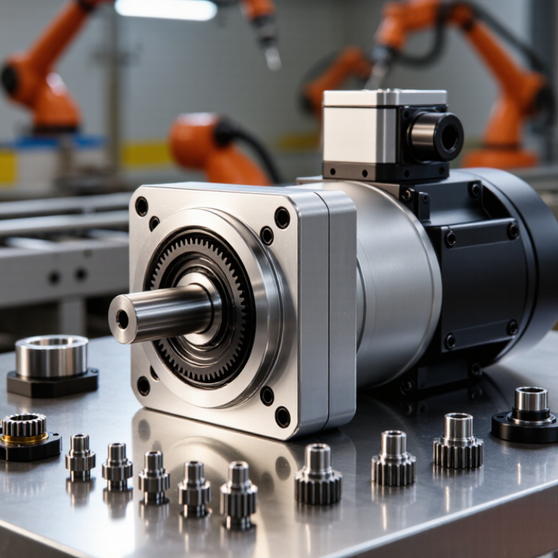
Why Choose a Customized Gear Motor?

What Is a Customized Gear Motor?

A customized gear motor is a motor and gearbox designed for a specific machine, rather than selected from a standard catalog. It combines electrical output with mechanical reduction. The result is controlled speed, useful torque, and a suitable installation size. Customization may include the gear ratio, shaft shape, mounting holes, voltage, connector, brake, or feedback sensor.

In practical engineering work, the required torque comes first. A conveyor moving wet containers needs different protection from a small indoor actuator. Engineers may adjust the gear teeth, housing material, sealing method, and thermal capacity. A 24-volt motor may suit compact equipment, while another application needs a different voltage and duty cycle. Noise also matters. A quiet office device cannot tolerate the sound of a poorly matched gearbox.

A reliable design begins with real operating data. Measure load, speed, starting force, running time, available space, and ambient temperature. Then test the motor under repeated cycles, not only during a short demonstration. I have seen promising prototypes fail because the starting torque was underestimated. That mistake is easy to make. It is also expensive. A customized gear motor may still require refinement after testing. Gear wear, heat buildup, or slight shaft movement can reveal assumptions that looked reasonable on paper. Careful documentation, sample testing, and clear performance limits make the final design more dependable.

How Custom Gear Motors Match Specific Application Requirements

Why Choose a Customized Gear Motor?

How Custom Gear Motors Match Specific Application Requirements

A customized gear motor begins with the application, not a catalog number. Engineers assess torque, speed, duty cycle, load direction, mounting space, and starting conditions. A conveyor carrying uneven cartons needs different behavior from a medical positioning table. The first may require shock resistance. The second may demand quiet, precise movement. Small details matter. Shaft alignment matters too.

The U.S. Department of Energy reports that motor-driven systems consume more than 70% of industrial electricity. This makes efficiency a practical design concern, not a marketing phrase. A correctly matched gear ratio can reduce wasted power and limit heat during continuous operation. The International Federation of Robotics recorded 541,302 industrial robot installations in 2023. That growth increases demand for compact motors with controlled speed, repeatable torque, and reliable feedback.

Customization can include winding selection, gear materials, lubrication, encoder integration, sealing, and connector placement. Environmental conditions must be tested honestly. Dust, washdown, vibration, and low temperatures can expose weak assumptions. A laboratory test may not represent a real production line. Engineers should compare measured temperature rise, noise, backlash, and efficiency against the application’s limits. A perfect specification is rare. We often revise the design after observing startup loads or unexpected vibration. That reflection improves reliability more than choosing the largest motor.

Why Choose a Customized Gear Motor? - How Custom Gear Motors Match Specific Application Requirements

Application Requirement Customization Approach Typical Engineering Parameters How It Improves Application Fit Design Considerations
Required output speed Select the gear ratio and motor winding to match the desired operating speed. Common gear ratios: 3:1 to 300:1; output speed depends on motor speed and ratio. Reduces the need for external speed reducers, belts, or electronic correction. Higher ratios generally increase torque while reducing output speed and may require additional gear stages.
Output torque Adjust the gear train, motor size, shaft diameter, and thermal design for the required load. Continuous torque is application-specific; peak torque is normally higher for short-duration acceleration or stall events. Provides sufficient starting and running torque without unnecessarily increasing motor size. Torque must be checked against duty cycle, shock loads, acceleration time, and service factor.
Limited installation space Modify the housing shape, mounting pattern, shaft position, and connector orientation. Possible configurations include inline, parallel-shaft, right-angle, and compact planetary arrangements. Allows the gear motor to fit within the available envelope and avoid interference with nearby components. Compact designs may reduce heat-dissipation area, so temperature rise should be verified.
High positioning accuracy Choose a low-backlash gear train and integrate an encoder or other feedback device. Backlash depends on gear type and manufacturing accuracy; precision gearboxes can be specified below 1° of angular play. Improves repeatability and helps the control system maintain accurate positioning. Encoder resolution does not eliminate mechanical backlash; the complete transmission must be evaluated.
Frequent starts and stops Optimize motor winding, gear materials, bearings, lubrication, and thermal capacity for intermittent duty. Duty cycles are commonly defined by operating time, rest time, starts per hour, and load profile. Supports repeated acceleration and braking with less risk of overheating or premature wear. Starting current, regenerative energy, and peak mechanical loads should be included in the design review.
Energy efficiency Match motor power, gear ratio, reduction stages, and operating point to the actual load profile. Gear-motor efficiency varies by gear type, ratio, lubrication, speed, and load; multi-stage reductions generally introduce additional losses. Reduces wasted electrical power and can lower heat generation during continuous operation. Efficiency should be measured at the intended speed and torque rather than judged only from nominal ratings.
Outdoor or washdown operation Specify sealed housings, suitable shaft seals, corrosion-resistant materials, and an appropriate ingress-protection level. Ingress-protection ratings such as IP54, IP65, or IP67 describe protection against dust and water under defined test conditions. Improves resistance to dust, moisture, and temporary water exposure when the complete assembly is correctly sealed. Connectors, cable exits, mounting interfaces, and shaft seals must meet the same environmental requirements.
Low operating noise Use helical or planetary gearing, optimized tooth profiles, balanced components, and vibration control. Noise is affected by speed, load, gear accuracy, housing stiffness, lubrication, and mounting conditions. Helps the equipment meet acoustic targets in medical, office, laboratory, and consumer environments. Noise specifications should state the measurement distance, speed, load, mounting method, and test environment.
Extended service life Size gears, bearings, shafts, and lubrication systems for the expected load spectrum and operating hours. Service life is commonly evaluated using bearing L10 life, gear tooth strength, wear limits, and thermal performance. Reduces unplanned maintenance and supports predictable replacement intervals. Contamination, shock loads, misalignment, inadequate lubrication, and excessive temperature can shorten service life.
Electrical and control compatibility Customize voltage, winding, sensors, brakes, connectors, and feedback options. Common low-voltage motor systems include 12 V, 24 V, and 48 V DC; voltage and current must match the controller. Simplifies electrical integration and allows direct compatibility with the equipment’s control architecture. Verify starting current, electromagnetic compatibility, braking requirements, connector ratings, and cable length.
Special shaft or mounting interface Adapt shaft diameter, keyway, D-flat, spline, flange, mounting holes, and output orientation. Interfaces should be defined by dimensional tolerances, fit class, runout, concentricity, and allowable radial or axial load. Minimizes adapters and reduces assembly time, alignment errors, and mechanical connection points. Output shaft loads must remain within the gearbox bearing and gear-capacity limits.

Note: The listed ranges and design practices are representative engineering references. Final gear-motor specifications should be verified against the actual load, speed profile, environment, duty cycle, mounting arrangement, and applicable safety requirements.

Key Benefits of Choosing a Customized Gear Motor

A customized gear motor matches torque, speed, load, and operating hours more precisely than a standard unit. That fit matters. The U.S. Department of Energy reports that motor-driven systems can consume 50% to 70% of industrial electricity. Even modest efficiency gains can therefore reduce long-term operating costs.

Customization also improves mechanical performance. Engineers can specify the gear ratio, shaft position, mounting pattern, braking method, and enclosure rating. A conveyor moving wet cartons may need sealed protection and corrosion-resistant materials. A packaging machine may need rapid starts, low backlash, and accurate positioning. The right configuration can reduce heat, vibration, noise, and premature bearing wear. Maintenance teams gain clearer access, too.

A customized gear motor can also prevent costly oversizing. An oversized motor often runs below its efficient operating range. That sounds safe, but it may increase energy use and reduce control quality. Lifecycle analysis remains essential, not just purchase price. The U.S. Department of Energy’s motor system guidance supports evaluating efficiency, controls, maintenance, and total operating cost together. Still, customization is not automatically better. Poor load data can produce an expensive mismatch. Measure real torque, peak loads, duty cycles, ambient temperature, and starts per hour before specifying the unit. Field experience helps, but assumptions can fail.

Why Choose a Customized Gear Motor? – Key Benefits of Choosing a Customized Gear Motor

A customized gear ratio helps match motor speed to the required application speed.

The chart shows theoretical output speed for a 3,000 rpm motor using different gear ratios. Output speed is calculated as motor speed ÷ gear ratio. A suitable customized ratio can improve speed matching, control, and system efficiency. Actual performance may vary because of gear friction, load conditions, and transmission efficiency.

Factors to Evaluate Before Ordering a Custom Gear Motor

Why Choose a Customized Gear Motor?

Factors to Evaluate Before Ordering a Custom Gear Motor

A customized gear motor can match a machine more precisely than a standard unit. Before ordering, define the required torque, output speed, duty cycle, and load pattern. A conveyor moving heavy cartons needs different gearing from a compact medical actuator. Check starting torque, not only running torque. Short overloads can damage undersized gears. Heat matters. Ask for thermal data at the expected ambient temperature, voltage, and operating hours.

Tips: Prepare a clear application sheet. Include shaft orientation, mounting dimensions, allowable noise, backlash, and cable position. Specify the real load, including friction and occasional jams. Measure twice. A drawing with one missing tolerance can cause costly revisions. Also request sample testing under actual conditions. Bench performance may not reflect dust, vibration, or repeated starts.

Material selection and gear geometry deserve careful review. Steel, sintered metal, and reinforced polymers behave differently under impact and continuous loads. Sealing requirements may change the housing design. Confirm insulation class, ingress protection, efficiency, and expected service life. Reliable suppliers should provide test records, dimensional reports, and traceable specifications. However, no calculation captures every field condition. Early prototypes may reveal unexpected noise or heat. That is not failure; it is useful evidence for refining the design before production.

How a Customized Gear Motor Is Designed and Developed

A customized gear motor begins with the machine, not a catalog. Engineers examine load, speed, duty cycle, available space, and operating temperature. A conveyor moving warm, dusty products needs different protection from a quiet medical instrument. We record real operating conditions, including brief overloads that specifications often miss. Small details matter. Shaft direction, mounting holes, cable exits, and allowable noise can change the entire design.

The development team then selects the motor type, gear ratio, materials, bearings, seals, and control method. Torque calculations guide the first layout, while simulation can reveal weak housing areas. Prototype units are tested for starting torque, efficiency, heat rise, vibration, and endurance. A practical test may run for days under changing loads.

Measurements are compared with design targets, not assumptions. The first design is rarely perfect. Gear noise may remain higher than expected, or the housing may waste valuable space. That feedback sends the team back to the drawings.

Reliable development includes traceable drawings, controlled revisions, and repeatable inspection procedures. Engineers verify critical dimensions with calibrated tools and review failure risks before production. Sample motors should be tested in conditions resembling the final equipment. This is where experience becomes useful, because laboratory success can hide installation problems. A connector may be difficult to reach. A seal may perform differently after repeated thermal cycling. Customer feedback, test data, and manufacturing limits shape the next revision. The result is a drive system designed around measurable needs.

FAQS

What is a customized gear motor?

It is designed for a machine’s specific torque, speed, load, and operating schedule. The design may include a special gear ratio, shaft position, mounting pattern, or enclosure.

Why choose a customized gear motor instead of a standard unit?

A closer fit can improve efficiency, control, noise, vibration, and service life. Standard units may work, but they can waste space or energy.

How can customization reduce operating costs?

Motor-driven systems can use much of an industrial facility’s electricity. Better sizing may reduce energy use, heat, and maintenance over the equipment’s working life.

What information is needed before designing the motor?

Engineers need real torque, speed, peak loads, duty cycles, temperature, and starts per hour. Available space and mounting details also matter.

Can an oversized motor create problems?

Yes. It may operate below its efficient range and provide weaker control. Bigger is not always safer.

What features might a difficult environment require?

A dusty or warm conveyor may need sealed protection, durable materials, and suitable bearings. Wet cartons can require corrosion-resistant parts.

How is a customized gear motor tested?

Prototype units are tested for starting torque, efficiency, heat rise, vibration, and endurance. Testing may continue for several days under changing loads.

Is the first design always successful?

No. Gear noise may remain too high, or the housing may occupy valuable space. The team should revise drawings after reviewing test results.

Why are installation details important?

Cable exits, shaft direction, connector access, and seal behavior can affect actual performance. Laboratory success can hide field problems.

Does customization always produce a better result?

Not automatically. Poor load data can create an expensive mismatch. Measure real conditions carefully, then question every assumption.

Conclusion

A Customized Gear Motor is a motor-and-gearbox solution developed around the specific needs of an application rather than selected as a standard, off-the-shelf product. By adjusting factors such as torque, speed, dimensions, mounting method, power requirements, duty cycle, noise level, and operating environment, it can achieve a closer match between the drive system and the equipment it operates. This tailored approach may improve efficiency, reliability, space utilization, and overall performance while reducing unnecessary compromises.

Before ordering a Customized Gear Motor, users should clearly evaluate load characteristics, available installation space, control requirements, environmental conditions, expected service life, maintenance needs, and project budget. The design and development process typically begins with requirement analysis, followed by motor and gearbox selection, mechanical and electrical engineering, prototype development, testing, and final refinement. Careful communication between the user and designer is essential throughout the process, helping ensure that the finished solution meets functional expectations and can be integrated smoothly into the target equipment.

Amelia

Amelia

Amelia is a seasoned marketing professional with a wealth of expertise in our company’s core offerings. With an unwavering passion for driving growth and innovation, she plays a pivotal role in shaping our marketing strategies and enhancing brand visibility. A key aspect of her responsibilities......