TeTe Motor
Automation is moving from isolated machines toward connected, measurable production lines. The 2026 Top Gear Motor for Automation Buying Guide examines the small mechanical decision behind that larger shift. A gear motor may drive a conveyor, indexing table, robotic axis, packaging feeder, or warehouse lift. Each application demands different torque, speed, duty, braking, and protection.
The International Federation of Robotics reported 541,302 industrial robot installations worldwide in 2023, with more than 4.28 million robots operating globally. Those figures show why dependable motion hardware matters. A failed gear motor can stop more than one station. It can leave operators waiting beside a silent conveyor. The U.S. Department of Energy also identifies motor-driven equipment as a major share of industrial electricity use. Efficiency is therefore an operating cost issue, not just a specification.
This guide compares the practical factors behind a reliable Gear Motor For Automation. These include gearbox design, rated torque, service factor, backlash, thermal performance, mounting position, encoder feedback, and drive compatibility. IEC 60034 motor standards and manufacturer test data provide useful reference points. However, catalog efficiency numbers may not reflect frequent starts, shock loads, poor alignment, or high ambient temperatures. That limitation deserves attention.
Real buying decisions need field experience. Measure the load. Record the duty cycle. Check the shaft and flange dimensions. Ask how the supplier verifies noise, temperature rise, sealing, and life expectancy. A cheaper unit can become expensive after repeated replacement. Yet premium pricing alone proves nothing. This guide encourages evidence-based comparison, careful questioning, and a little healthy doubt before selecting equipment for demanding automation.
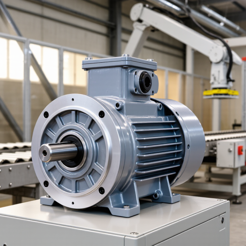
A reliable gear motor begins with torque, speed, and duty, not catalogue size. The IEA reports that electric motor systems consume more than 40% of global electricity. Small efficiency errors can therefore become expensive across continuous automation lines.
Use P=Tω to connect mechanical power with output torque. Here, P is watts, T is newton-metres, and ω is radians per second. A 1.5 kW motor running at 150 rpm produces about 95.5 Nm before gearbox losses. Real output will be lower.
Gearbox efficiency, acceleration, and shock loads must be checked. A conveyor may need high starting torque, even when running torque looks modest. That detail is easy to miss.
Duty matters just as much. IEC 60034-1 defines S1 for continuous duty, S2 for short-time duty, and S3 for intermittent periodic duty. S6 covers continuous periodic operation with load and no-load periods. Choose the S class from the actual cycle, including starts per hour and stopping time. The European Commission’s Motor Systems analysis identifies operating conditions and load matching as major efficiency opportunities. Nameplate power alone is not enough. A spreadsheet may still mislead. Measure the load.
For procurement, record speed, torque, duty cycle, ambient temperature, mounting position, braking needs, and permissible backlash. Then verify thermal capacity under the worst cycle, not the average one. Expect to revise the first selection. Automation rarely behaves perfectly.
Sizing the gear train starts with measured load data, not catalogue torque. ISO 6336 evaluates cylindrical gear teeth for bending strength and contact fatigue. Record output torque, speed, acceleration, starts per hour, shock, and operating hours. Then calculate the design torque using the application service factor. A conveyor with smooth loading may require a lower factor than a indexing table with repeated impacts. Values must follow the supplier’s duty classification and the actual machine profile.
The International Federation of Robotics reported 541,302 industrial robot installations in 2023, showing continued demand for compact, repeatable motion systems. More automation also means more frequent starts and reversals. That duty can raise thermal stress, even when average torque looks modest. Check ISO 6336 ratings at the required speed, temperature, lubrication condition, and lifespan. Do not compare nominal ratios alone. Small errors compound. A practical design may use a 1.25 service factor for steady loading and a higher factor for shock, but these figures are only starting points. Confirm them against ISO 6336, the manufacturer’s testing data, and your measured cycle. The ISO standard does not replace field validation. Misalignment, poor lubrication, and brief overloads can reduce real service life. I would also leave a documented margin, rather than selecting the smallest motor that passes a spreadsheet.
Sources: ISO 6336-1:2019 and International Federation of Robotics, World Robotics 2024.
When selecting a gear motor for automation, compare IE3 and IE4 efficiency under IEC 60034-30-1. The standard classifies efficiency for specific electric motor designs and operating conditions. It does not guarantee identical savings across every machine. IE4 motors usually reduce electrical losses, especially during long shifts and steady loading. Yet a lightly loaded motor may deliver smaller savings than expected. Check the rated power, speed, torque, and duty cycle before choosing.
In factory assessments, I have seen motors run below 50% load for most of the day. That weakens the financial case for upgrading. Measure real current and operating hours, not only the nameplate data. For a conveyor operating 20 hours daily, even a small efficiency gain can reduce heat and energy consumption. Confirm compatibility with the gearbox, inverter, braking system, and mounting dimensions. IEC 60034-30-1 is useful, but the complete drive system matters more.
Backlash deserves measurement, not a marketing promise. In field commissioning, even a small angular gap can become visible at the gripper. Specify backlash in arcminutes, with the applied load, speed, and measurement direction recorded. A no-load figure may look excellent. It may disappoint under reversal.
The 2024 World Robotics report recorded 541,302 industrial robot installations worldwide in 2023, a 10% annual increase. More robots mean tighter expectations for repeatability.
A gear motor should be tested at the machine’s real duty cycle, not only on a clean bench.
Thermal limits are equally practical. The U.S. Department of Energy’s Industrial Motor System Market Assessment reports that motor-driven systems use about 69% of manufacturing electricity. Heat affects lubricant life, winding insulation, encoder stability, and positioning drift.
Check ambient temperature, mounting orientation, duty cycle, and allowable surface temperature.
IEC 60529 defines IP protection levels, but IP65 means dust-tight and protected against water jets. It does not confirm immersion resistance, chemical resistance, or a sealed cable entry.
An IP rating can be technically correct and still be unsuitable. A neat specification sheet can mislead. Leave safety margin, then verify it with a loaded thermal test.
A gear motor for automation should be judged by control quality, not torque alone. A high-ratio gearbox may deliver force, yet backlash can weaken positioning accuracy. Select feedback that matches the motion task, such as an encoder for indexing or a resolver for harsh temperatures. The IEA reports that motor-driven systems consume roughly half of global electricity. Efficiency deserves serious attention.
Functional safety must be engineered into the complete drive system. Check Safe Torque Off performance against IEC 61800-5-2 and verify the required Performance Level under ISO 13849-1. Confirm reaction time, diagnostic coverage, braking behavior, and restart prevention. A safety input on the motor is not automatically a safe machine. Test the actual wiring and controller logic. Small assumptions become expensive faults.
EMC testing should use the final cable length, grounding method, and enclosure layout. IEC 61800-3 provides a practical framework for drive-system emissions and immunity. Measure noise near sensors, communication cables, and safety circuits. Lifecycle cost includes energy, lubrication, thermal derating, spare parts, and unplanned downtime. U.S. Department of Energy motor-system guidance shows that operating energy can dominate motor ownership cost over time. My own buying mistake was comparing purchase prices before estimating stoppage costs. A spreadsheet can still mislead. Require field data, maintenance records, and a documented acceptance test before approval.
| Gear-Motor Technology | Typical Automation Applications | Typical Continuous Output Torque | Typical Output Speed Range | Feedback Capability | Positioning and Speed Control | Functional Safety Readiness | EMC Considerations | Expected Maintenance Profile | Relative Lifecycle Cost | Best-Fit Assessment |
|---|---|---|---|---|---|---|---|---|---|---|
| AC Induction Gear Motor with Variable-Frequency Drive | Conveyors, mixers, pumps, fans, packaging lines, and simple material handling | Approximately 5–5,000 N·m, depending on frame size and gearbox ratio | Approximately 5–300 rpm at the gearbox output | Optional Incremental encoder, resolver, or no feedback |
Good for continuous speed control; limited positioning performance unless paired with closed-loop control | Medium Safety functions normally reside in the drive or safety controller, such as Safe Torque Off |
Use shielded motor cables, correct grounding, drive filters where required, and separation from sensitive signal wiring | Low to medium; inspect bearings, seals, gearbox lubrication, and cooling paths | Low Usually economical for constant-speed or moderate-control applications |
Strong fit when cost, robustness, and continuous operation are more important than rapid positioning |
| Permanent-Magnet AC Servo Gear Motor | Robotics, indexing, electronic camming, coordinated motion, filling, cutting, and high-speed packaging | Approximately 0.5–1,500 N·m, with short-term peak torque commonly above continuous torque | Approximately 10–1,000 rpm at the gearbox output, depending on motor and ratio | Integrated or Required High-resolution encoder or resolver for closed-loop control |
Excellent positioning, acceleration, repeatability, and synchronized motion performance | High Compatible with drive-based safety functions, but the complete machine must be validated to the required PL or SIL |
Requires careful cable shielding, bonding, grounding, encoder wiring, and drive-filter selection to control conducted and radiated emissions | Low to medium; monitor bearings, seals, gearbox backlash, lubrication, and feedback-device condition | Medium to High Higher purchase cost can be offset by throughput, accuracy, and reduced setup waste |
Best fit for demanding motion profiles, high repeatability, and coordinated multi-axis automation |
| Brushless DC Gear Motor | Compact conveyors, automated doors, laboratory equipment, small actuators, and battery-powered machinery | Approximately 0.05–200 N·m | Approximately 10–500 rpm at the gearbox output | Commonly Available Hall sensors for commutation; encoders for closed-loop control |
Good speed control and moderate positioning when an encoder and suitable controller are used | Medium Safety capability depends primarily on the controller, power stage, and system architecture |
Fast switching edges can create electromagnetic noise; use proper motor leads, suppression, grounding, and controller layout | Low; no brushes to replace, but gearbox wear and bearing life remain important | Medium Efficient operation may reduce energy cost in duty cycles with frequent speed changes |
Good fit for compact, efficient equipment requiring moderate torque and low maintenance |
| Stepper Gear Motor | Labeling, low-speed indexing, valves, feeders, inspection stages, and light-duty positioning systems | Approximately 0.1–100 N·m, with torque decreasing as speed increases | Approximately 1–150 rpm at the gearbox output | Optional Often open-loop; encoder feedback can be added for stall detection and correction |
High low-speed holding torque and simple indexing; risk of lost steps under overload without feedback | Low to Medium Safety functions generally require an external drive, contactor, brake, or safety-rated control solution |
Driver switching can produce noise; apply cable shielding, grounding, current tuning, and physical separation from feedback cables | Low; gearbox lubrication, bearings, and thermal loading require periodic review | Low to Medium Attractive for simple motion, but oversizing and heat can increase operating cost |
Best fit for economical, predictable, low-speed indexing where acceleration and dynamic performance are modest |
| Integrated Servo Gear Motor | Distributed conveyor zones, autonomous machines, modular packaging equipment, and space-constrained installations | Approximately 0.5–500 N·m | Approximately 5–600 rpm at the gearbox output | Integrated Encoder or resolver connected directly to the internal drive |
Excellent local motion control with reduced cabinet wiring and shorter commissioning time | High May support certified drive safety functions; verify the exact safety architecture and diagnostic coverage |
Motor-integrated drives can simplify wiring but may increase local emissions; follow installation limits for grounding, cable length, and network routing | Low to medium; fewer external components, but electronics are exposed to heat, vibration, and contamination at the machine location | Medium to High Reduced panel space and wiring can lower installation labor and total machine footprint |
Strong fit for decentralized automation where cabinet reduction and fast machine integration are priorities |
| AC Synchronous Gear Motor with Closed-Loop Drive | Energy-efficient conveyors, high-duty-cycle equipment, pumps, fans, and applications with stable speed requirements | Approximately 2–2,000 N·m | Approximately 10–400 rpm at the gearbox output | Available Encoder or resolver feedback is used when high accuracy or load monitoring is required |
High efficiency and stable speed regulation; positioning capability depends on the selected drive and feedback system | Medium to High Safety performance depends on the certified drive functions and the validated machine control system |
Drive-generated common-mode currents and switching noise require appropriate bonding, filtering, and cable installation practices | Low to medium; review gearbox lubrication, bearings, seals, and thermal conditions | Medium Higher initial cost may be justified by energy savings in long-running applications |
Good fit for high operating hours where efficiency and speed stability influence total cost of ownership |
Record output torque, speed, acceleration, starts per hour, shock loads, and operating hours. Catalogue torque alone is insufficient.
It increases design torque to reflect shock, starts, reversals, and real operating conditions. Smooth conveyors may need less margin than indexing tables.
No. It is only a starting point for steady loading. Repeated impacts require confirmation through testing and duty classification.
The standard evaluates gear tooth bending strength and contact fatigue. Check ratings at the required speed, temperature, lubrication condition, and lifespan.
Not reliably. Frequent starts and reversals can create thermal stress, even when average torque appears modest.
Specify backlash in arcminutes, with load, speed, and measurement direction included. A no-load value may look excellent, then disappoint during reversal.
Check ambient temperature, mounting orientation, duty cycle, surface temperature, lubricant life, and winding insulation. Loaded thermal testing is worth the time.
No. It indicates dust-tight construction and protection against water jets. It does not confirm immersion resistance, chemical resistance, or sealed cable entry.
Usually not. Leave documented margin and validate the result under the machine’s real cycle. A spreadsheet can still be wrong.
Choosing the right Gear Motor For Automation begins with matching torque, speed, and operating duty to the machine’s real requirements. Use the relationship P = Tω to estimate power, then apply IEC 60034-1 duty classes to account for start-stop cycles, load variation, and thermal limits. The gear train should be sized with ISO 6336 rating methods and suitable application service factors, ensuring reliable performance under shock, acceleration, and continuous operation. Efficiency is also essential, so comparing IE3 and IE4 motor options under IEC 60034-30-1 can help reduce energy consumption and operating costs.
Beyond basic power transmission, automation applications demand precision and dependable protection. Evaluate backlash, temperature limits, enclosure ratings under IEC 60529, and the suitability of feedback devices such as encoders. The final selection should also consider functional safety, electromagnetic compatibility, maintainability, and total lifecycle cost. A properly specified system delivers accurate motion, stable operation, easier integration, and long-term value.
